maandag 12 september 2011

Mala Frontend Layout

Found this site, http://malafe.net/

check out the Layouts for examples. Some very nice ready to download or to give inspiration to create one yourself.
My favorite so far:  the Mameroom

woensdag 7 september 2011

Almost finished

The end result! What fun it was to create this. There are a few things left to make it 100%
- The bezel exists of 4 seperate pieces mounted together, this will be replaced by one piece of wood using a router. But this takes some practice and maybe a router table to make it easy.
- To Power up the system you have to remove the backdoor and push the original pc switch. It's cooler to have the switch at the back, not such a problem to fix.
-Clean up the wires inside the cabinet. Lot's of loose cables have to be tight together.

-Create a MAME fronted. Í'm still a bit in doubt wich one to use. Hyperspin looks great but it's a bit too much. Not running so smooth on this setup. MALA and Maximun Arcade look promising. I'm not realy interested in the other emulators, only MAME.  An article about this will be written in the blog if i spent some more time on this!
The backdoor. What to tell ;) The 2 green buttons at the top left are on this foto not mounted correctly yet. They are pushed back in the wood now. The function of these are TEST SW and SERVICE SW, meant for original PCB'S.
I read somewhere a tip to place a black&white print behind the color print to protect the darkcolors from being over-lighted. Tried this but it blurred the whole picture. Now it's very bright, with the disadvantage of the dark parts over-lighted. The Marquee is printed on a high quality laserprinter on normal paper. A wish for me is to order the same picture at quality material, like they do at gameongrafix etc. On the wishlist!

The plexi was cut with the smallest jigsaw blade available in the local store. It's a 1-2mm metal blade. They normally cut anti-skid board with it for instance.
Worked well. Cut a medium speed, not to slow and fast or it will break/melt.

The Arcade powered on! My son playing Sega Hang-On. He likes the race games. Enduro Racer, Crazy Race, Outrun.


maandag 5 september 2011

Painting

After the sanding and putty prepartion on the wood 2 layers of primer were done.
Last week I painted the cabinet totally black but was really not pleased at all with the result. It looked to 'hard' for a kids room. So I decided to get rid of the black on the side of the cabinet, prime it once more and paint it with a orange tone matching the side art stickers color scheme (see previous blog post)

In total 3 ground layers and 3 color layers.

paint details:
side: Histor Satin flexa colors e3.35.72
kickplate: Histor Satin black 6372


Marquee preparation

Look here the preparation of the marquee. The TL is from the kitchen, we have a kitchen that is 15 years old falling apart. 

The TL has a new purpose!


2 speaker grills get mounted. The holes are drilled with a special hole drill. I experienced you have to slowly presure the drill and increase speed slow for maximum result. To much preasure and the drill gets stuck.

woensdag 31 augustus 2011

Inside the cabinet

No concern about space inside the cabinet there is room enough for the hardware. Except maybe a SNK Neo Geo board, but I'll keep that board for another project.

First thing mounted is the power connector box and shortened all power cords.
For the TL behind the marguee,  for the audio setup, for the PC power adapter and one for the monitor.


The motherboard and J-Pac are mounted with some PCB mountingfeet.

equipment: AMD Sempron 3000, gigabyte motherboard from a former Packard-Bell pc.Wifi card,  Philips stereo soundsystem with subwoofer (he, why not :). DELL 17"monitor TFT and a really quiet DELL PSU from an optiplex GX280. 64mb AGP card (needed for performance! see previous blog message)
The wires on the harness are taped together. I advise you to do this or else everything gets messed up. I'll fix the rest of the wires after connecting the firebutton 4,5 and 6 to the J-PAC (since the standard jamma harness can only connect button 1,2 and 3). One of the power connectors from the PSU is used for Grounding (black), the yellow cable for 12v in the iluminated credit button and the red one is terminated. If i'm correct you can use the red cable if you have LED lights. The board is powered up by the button from the orignal casing, i'd like to change this to something accessible from outside of the cabinet. But for now it's ok this way.


maandag 22 augustus 2011

Computer problems solved

Thanks to the help of forum members at http://www.arcadecontrols.com/ i've figured out what the cause of the performance delay was. It's the onboard VGA card.

This takes a part of processor time / memory sharing, leaving less available for MAME emulation. For that reason now the system uses a dedicated AGP VGA card 64MB.

The classic games run smooth now! thanks again, discussion can be followed here.

zondag 21 augustus 2011

J-PAC problems

A small update.
I lost some time with testing the J-pac. The board I had was corrupted. Questions and answers about Ultimarc hardware can be found at http://www.mameworld.info
check this link for the problem with my hardware: Mameworld Forum

It works now with a new board. But now the second problem; the PC seems to slow to my surprise. It runs on a AMD Sempron 3000, 1.8ghz Windows XP.
Still, if you run Bagman or Donkey Kong it's so slow, there is too much delay. How is this possible since Mame cabinets are build since 15 years now or something and this PC is from 2006. If anyone has an idea please let me know. I'm going to replace the hardware next week, but i'm curious why itt doesn't run fine on this PC hardware.

woensdag 17 augustus 2011

Electronics, Wiring

Have to be carefull with this and not short circuit the board.

Last year I bought a 60 in 1 card for my original cabinet ( Time Pilot / Konami ). This card helped me to test the buttons and joystick since you don't have the trouble of (mis) configuring a mame engine. (and loose a lot of time).

The cabinet will be Jamma 'ready'. I like to have the oppurtunity to place a real board if I want to and stay close to an original cabinet..

what you need for this:

- A Jamma Harness
- A Jamma Harness pinout document
- Wires for ground. and Ebay some offer a daisy chain wire with clamps pre-attached.
- A joystick and buttons. 6 fire buttons, player I/II, credit button, Test Button, Service button
- A PSU ATX. A simple PC power supply will do. There are PSU's on ebay offered simular to the ones in the original cabinets.

To understand how to wire the microswitches this is a good source http://arcadecontrols.com/arcade_wiring.shtml basicly what it's all about is to place the Ground on the COMMON and the corresponding Jamma wire to the Normally Open.

The pinout, just an example there are lot on the internet. I had another one with the colors described but it was not a perfect match on the harness. It's not hard to figure out since the numbers and letters are printed on the connector (parts side, solder side)


Once hooked up to the connector power it on. To kickstart the PSU use this trick, find the green wire on the ATX connector and loop it to a black cable (pin 20 or 24)


powered on:
So fare the electronics outside of the cabinet. It helped understanding the Jamma Connector. In a next update all hardware and wires are build in the cabinet.

woensdag 3 augustus 2011

Control Panel

For the control panel I've choosen to give it a wood structure look. It's build of 2 layers the first of normal 12mm thick wood, the same as used for the kickplate and top of the cabinet where the marquee is placed.

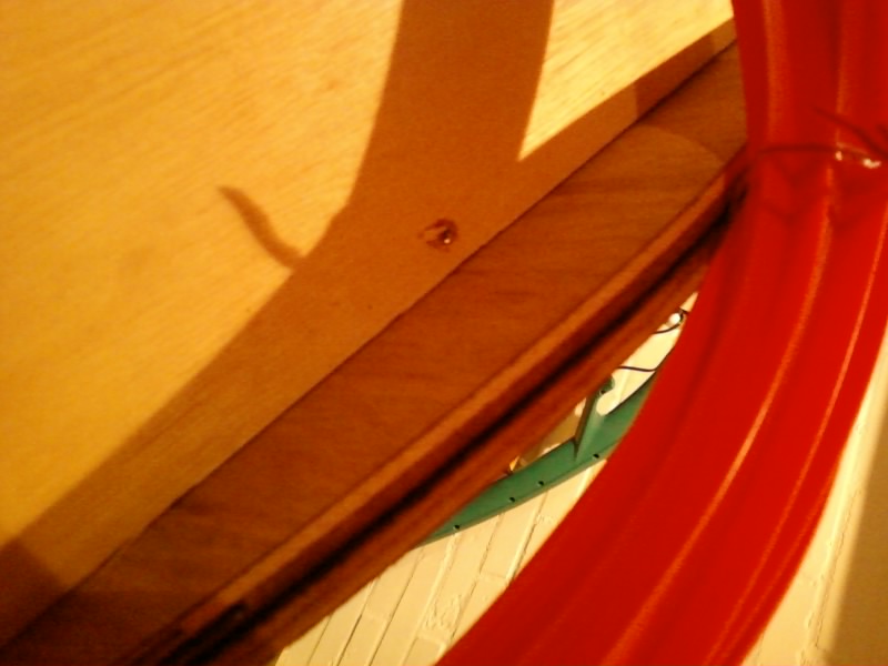
The first layer is for stability of the panel.


The next layer is some piece of floor laminate. Very strong material not sensitve for scratches.


Another idea next time would be using a plastic laminate on the first layer and finnish it off with some plexi glas. That would look very cool as well and you can place some sticker art underneath the plexi.


Bizon Polymax kit/glue is use to glue both layers to eachother. The clamps hold its together for a few hours.

Next step: drilling the holes in the panel.

For this usefull information can be found at the slagcoin website, check here. It makes you think how to position the buttons and why. I drawed a raster on the panel and placed both hand on it to imagine how the postion of the buttons and joystick would be.
This is very important because if you just take a wild guess it might turn out very uncomfortable playing on the cabinet.
Once painted on the panel drill the holes with a spade bit.  Start slow and more presure during the drilling.


Now I realised both layers are too thick if you place the joystick under the first layer. The stick would popout only 2 cm! To solve this I had to cut out a square in the first layer with a chisel.

     Since the panel has buttons on top and on the frontside space can become very tight. For instance originally I had the player 1 button on the left side next infront of the joystick. But this did not fit because of the lengt of the button. It hits the joystick. For that reason P1 and P2 are moved to the right and the drilled hole is used for a credit button!
A green illuminated button, think it looks very nice. See here the endresult. In a next blog update the electronics are shown in more detail.
 

maandag 1 augustus 2011

Some more woodworking

Back from vacation. Time to continue with the project.
The next action planned is preparing the t-molding with the router.
These are videos on youtube that give you a good impression on how to do this.
this one and this one. Some tips I ran into. The router bit was sold out at t-molding.com so I bought it at a woodworking shop. The type of bit you need is a slotting cutter 1/16" http://www.mlcswoodworking.com/orderstatus/html/smarthtml/pages/bt_slot.html

check your router if it's capable to mount the 1/4 or 1/2 inch shank set. Because mine didn't at first. The dutch term for this is "spantang". In europe the standard is in general the 1/2 inch. Most routers will support both but you better be sure or it will give additional costs.

It's real important to screw the bit very tight in the machine. I did not the first two times and the result was a ninja star flying around in the garage and the second time I almost screwed the whole cabinet by damaging the wood that had to be fixed with wood putty.

Another tip: do this outside or your house stinks like hell because of the smoke that comes out of the cabinet if you put the router on it. If you now think what an amateur your absolutely right nothing new here :)

I think this could be a combination of 2 reasons, one I have the router rotation set too high so the wood can't handle the warmth or it is because of the plywood as I'm pretty sure cutting in MDF goes much smoother.

But the result is what counts, here it is.


woensdag 20 juli 2011

Building the cabinet

The photos are transfered from my mobile, so here another update of the cabinet so far


The wood is plywood. Looks very nice unpainted already if you ask me. The first thing I did is stabalise the cabinet. So it holds itself together. I prefered this method because now it becomes visible of what you make and adjust anything you like.

Most cabinets are build with a predefined plan. Designed on paper with al measures set etc. I guess it depends on what you prefer. Technically I think making a plan is wiser to do, but this works for me.

Some more about the wood. Plywood is strong ans has a nice structure and colour. But most cabinets are build of MDF material.

MDF material has a smoother surface wich is better to paint and the wood is easy to work with. Also it's much cheaper compared to plywood.


Ooops miscalculated a bit here, yes the marquee part is a bit off at the lower part. Will correct that.


Room enough for the computer hardware. The control panel part is attached with a so called piano hinge.

I removed it again because there is a lot of work to do on the control panel. And this part attached at this moment is just not so clever :) 
The monitor inserted, a 17". The angle of the monitor set.


maandag 18 juli 2011

Side art arrived

Today the stickers arrived! I ordered them on Ebay from Idoluxman in Israel. They are originally intended as wallstickers, but in this case they can be used perfectly on the cabinet. I checked some sites offering side-art but the price is far to high and doing painting/printing myself is something I don't wan't to loose too much time on in this project atleast. Maybe for a next project.

The material looks like good quality suited for cabinet art.

How it starts

It starts with deciding on what to make. A full scale cabinet, a Bartop (Barcade) or a mini cabinet.
I had some wood already from repairing the house last summer so that could be used again. I decided to go for the mini-cabinet. Looking at the measures i'd more say a midi cabinet because it can be made smaller if you want.

OK, next decission is the style of the cabinet. There are so many nice examples of classics designs and projects with custom designs. The classic Pacman style cabinet is one of my favourites.

this is an example of such cabinet:
The measures are 41cm width and 122cm high.
The wood I had was 244cm this cut into 2 pieces gives the 122cm

41cm is based on the 17" monitor plus some space left for  monitor bezel.

An exact building plan with all measures and a term/verb list will be posted and linked in one of the next updates.


The sawing:

The 244 was cut into 2 pieces and placed on top of eachother tight together by clamps. You really need clamps to get an exact match of the sawing at both sides.

Now it's time to draw the outlines of the cabinet to get the shape ready. To get the upper side smootly drawn i used a lineal with a pencil attached to it. Center the lineal somewhere next to the board and draw the (part of) the circle on the wood. The result is a perfect round corner.

This method is used to draw the angle just above the middle and the part at top of the cabinet with slightly round angles.

After this was done it's sawing time with the Jig Saw.

zondag 17 juli 2011

Mini Arcade!

Something I've wanted to do for weeks finally started. Maintaining a blog about the cool project i started a few weeks ago. Building an arcade! The idea is to make it for my son, but to be honest i'm also enthousiast because of the nostalgic feeling i have with these machines!

I remember the days on vacation with my parents during the 80's early 90's spending time in the arcade hall of the resort playing Galaga and score a free play on the pinball machine. That was great.
Remember other game titles as Outrun, Afterburner, Supersprint. Maybe more pop up during this blog.

Anyway what triggered me to get this thing started was the movie 'A fistful of quarters'. A must-see for arcade fans. It made me curious about todays arcade scene and so i discovered the whole MAME community. To my surprise the arcade scene is very active. Maybe not that much in the Netherlands, but still on internet there is a lot to read and discover about this.

Anyway, back to the reason to create this BLOG :)

Owning an arcade is fun, building even more. 

As written, i've started building, i'll post the photos in the next updates so you can see what left to do. Also in this BLOG tips and tricks i ran into. I'm not that experienced with wiring and woodworking so if you dive into some kind of same project there might be something usefull to read for you.